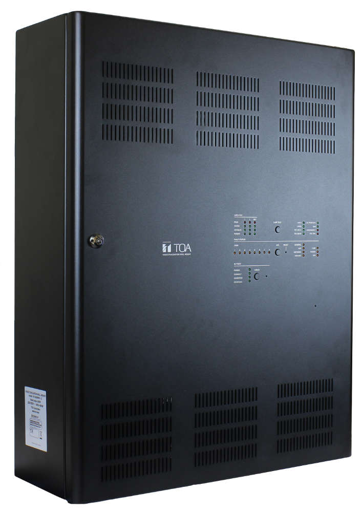
VX-3308WM
Wall-mount voice alarm system
- Complete PA and VA system in one unit, including power supply and power amplifiers
- Compact, flat unit that can be mounted in narrow environment (e.g. corridor)
- Cost and time effective: all components and two 300 Watt amplifier modules pre-assembled and connected
- One optional amp can be added
- All indications and controls according to EN 54-16
- Fault status indication for each speaker line
- Operation and audio signal status indication per amplifier
- 8 control outputs by open-collector-transistor and 4 by 5 A relays
- 16 standard and 2 voltage-controlled control inputs with monitoring
- IP network-based, max 160 units can be combined
- Fully compatible with the (rack-mounted) VX-3000 system
- Specifications
- Application examples
- Equipment
- Tender text
- Downloads
| VX-3308WM | |
|---|---|
| Power source |
220 - 230 V AC, 50 / 60 Hz Battery 2x 12 V |
| Power / current consumption |
1100 watts (at rated output incl. charging), 460 watts (EN 60065) |
| Frequency response |
40 Hz - 20 kHz |
| Audio input |
4 balanced audio inputs, sensitivity -20 dBV (line)/-60 dBV (mic), impedance: 47 kohms, phantom power 24 V selectable by software. 2 remote microphone inputs for up to 8 units. |
| Audio output |
8 speaker lines isolated from earth |
| Control input |
16 (contact), 2 (voltage controlled), all with surveillance |
| Control output |
8 (open collector, no-voltage make contact, control current max. 10 mA, withstand voltage 28 V DC, on RJ45 jack). 4 (no-voltage make contact, relay contact (NC, NO, C), control current: 2 mA to 5 A, withstand voltage: 125 V AC, 40 V DC, Connector: removable terminal block (12 pins) |
| Operating temperature |
-5 °C to +45 °C (23 F to 113° F) |
| Finish |
Steel plate, black (RAL 9011 or equivalent) |
| Dimensions |
550 x 700 x 200 mm (W x H x D) |
| Weight |
33.1 kg |
| Distortion |
≤ 1 % (at 1 kHz) |
| Current consumption |
25 A from battery max. |
| S/N ratio |
60 dBA (or better, at DA control link) |
| Indicator |
AC Power in (green) ×1, Run (green) ×1, Emergency (red) ×1, CPU Off (red) ×1, LAN A (green) ×1, LAN B (green) ×1, RS Link A (green) ×1, RS Link B (green) ×1. Fault Status (yellow): General ×1, Unit ×1, Network ×1, EMG Mic ×1, Fuse ×1, Power ×1, CPU ×1, Zone ×8. Amplifier: Peak (red) ×3, Signal (green) ×3, Operate (green) ×3, Power (green) ×3. Battery (green): Charging ×1, Battery power ×1, connection ×1, condition ×1 |
| Connection |
AC-mains: 2 pin screw terminal at breaker, 1 screw terminal for earth Speaker outputs: 6-pin removable screw terminal block ×4 Control inputs: 9-pin removable screw terminal blocks ×3 Emergency control inputs: 5-pin removable screw terminal block ×1 Control outputs: 9-pin removable screw terminal block ×1, 12-pin removable screw terminal block ×1 Network: 9-pin removable screw terminal block ×2 Internal connections: DC power supply (max. 25 A): 2-pin screw terminal ×1 DC power supply 24 V DC, 0.3 A: 4-pin removable screw terminal block ×1 |